Recommendation Thick Lens Formula Derivation

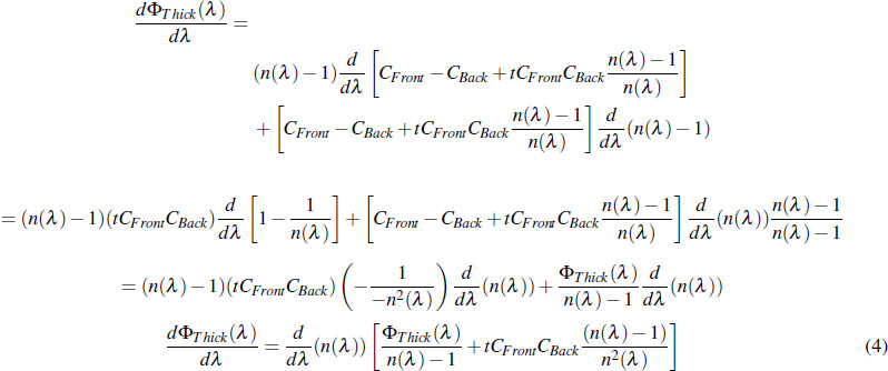
A final formula for the thick lens equation is rather unwieldy.
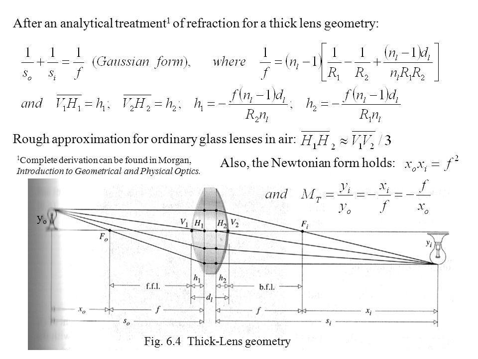
Thick lens formula derivation. The on-axis object is located 15 units in front of the first lens. The image formed by the first surface is treated as an object for the second surface. My textbook states that for thin lens formula of lens is ie 1 v - 1 u 1 f and for thick lens 1 v t 1 u t 1 f While the derivation is only given for thin lens i.
Lens 1 is the aperture stop for the shown position of the object. The length between and is nearly equal to of the length between and for ordinary glass lenses in air. It is also the entrance pupil since there are no optical elements located in front.
That central ray is propagated to define the optical axis further in the optical train which need not be in the same physical direction such as when. The thin lens equation cannot be used directly to find images formed by thick lenses. Equation 7 is used in special case where the lens is placed in a medium other than air.
Here we have assumed that the lens used is a thin lens. Even when Gullstrands equation is used to find the equivalent power of the thick lens that power is with respect to a principal planeThe thickness of the lens alters the image position and the center of the thick lens cannot in general be used as the lens position. The thin lens formula 1f 1v 1b see diagram below is often used to model how a 35mm camera lens works.
Matrix method thick lens. Frac1v-frac1ufrac1f Lens Formula Derivation. It turns out that the opticalpower of the thick lens called its equivalent power is given by FF1F2-tnF1F2.
The general problem of refraction by a thick lens is solved by applying the equation for the refraction at one surface to each surface in turn. Thick Lenses When the thickness of a lens is not negligible compared to the object and image distances we cannot make the approximations that led to the thin lens formula and requires a few additional parameters to describe it Front and Back focal lengths Primary and secondary Principle planes 3. The ray tracing technique is based on two reference planes called the input and output planes each perpendicular to the optical axis of the system.


